Home › Unlabelled ›
Water Tank Level Controller Circuit Diagram : Automatic Water Pump Controller Circuit For Submersible Motor Using 555 / In dollar it should be less than 1$.
Water Tank Level Controller Circuit Diagram : Automatic Water Pump Controller Circuit For Submersible Motor Using 555 / In dollar it should be less than 1$.. Automatic water level controller circuit is a simple engineering electronic. Automatic water tank level controller with dry pump run protection using arduino + ultrasonic sensor. The above mentioned circuit consists of four probes arranged in an overhead tank and are interfaced with port 2 of the microcontroller. Parts list the small circuit built around ic1 draws no current and therefore no voltage drop is generated across r5. The entire assembly, along with the power supply, should.
The probes are arranged in order on a pvc pipe according to the depth in the tank. Water or any liquid saving tanks are commonly used on commercial or industrial level and with these tanks motor or pumps are normally used for maintaining the desired liquid level. The trigger pin of the ultrasonic sensor is connected with pin number 7 of the arduino. The distance between the circuit and the water tank can be up to 50 meters. First, you should prepare following materials to make this setup.
Certain provisions are provided in the tank, so that we can automatically control the water level. The probes are arranged in such a way that they sense ¼th, 1/2, ¾th and even full levels as they are placed with equal spacing one. This video is about fully automatic water level controller pcb kit with all awesome features like dry run sensor, source tank. In dollar it should be less than 1$. The outflow rate depends on the diameter of the output pipe, which is constant, and the pressure in the tank, which varies with water. The ends of probes are connected to corresponding points in the circuit as shown in circuit diagram. The distance between the circuit and the water tank can be up to 50 meters. This voltage is safe on outdoors water tanks. This is a very useful circuit for household water tank. This circuit control the overflow of water and also indicate the level of the water in the tank. This arrangement is encased in a pvc pipe and fixed vertically on the inside wall of the water tank. The above mentioned circuit consists of four probes arranged in an overhead tank and are interfaced with port 2 of the microcontroller. In this project, we will be discussing the design of.
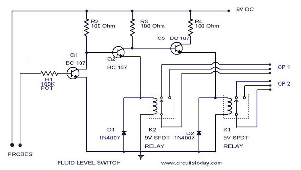
A simple but very reliable and effective water level controller circuit diagram is shown here. Parts list the small circuit built around ic1 draws no current and therefore no voltage drop is generated across r5. You are able to utilize this motor. Water level control is highly important in industrial applications such as boilers in nuclear power plants. As we know the length of water tank then we can calculate the water level by subtracting resulting distance coming as shown in the water level controller circuit given below.
Fully Automatic Water Level Controller Model No It180wlc Remote Control Switches Imagine Technology from imaginetech.in Using simple transistors and led's to determine the level of water level indicator & controller: Implement a water level controller using the fuzzy logic controller block in simulink. Each sensors float is suspended from above using an aluminium rod. It does this turning on and off a water pump depending on the status of sensors. The page coolly points out a surprisingly water level controller circuit using ic 555 which could be build by just about any new hobbyist for own operation. Ic2a, ic2b and q1 are wired as a. If you are using ic555, the circuit components are mentioned in the circuit diagram. Water level indicator indicates the level of the water present in the tank.
This low cost water level controller circuit when built and installed will very efficiently control the level of water inside any water tank to which it's readers may refer to the adjoining pin out diagram of ic4093 for further ease of construction.
First, you should prepare following materials to make this setup. Water tank alarm/indicator/detection/sensor/meter/gauge circuit.electronics projects. Liquid level controller circuit design, simulation and pcb layout design using proteus ide. Automatic water level controller circuit is a simple engineering electronic. This water level controller circuit can control the water level in a tank. The circuit uses 6 transistors, 1 ne555 timer ic, a relay and few passive components. Water level indicator circuit diagram with alarm electronic design or schematic. Parts list the small circuit built around ic1 draws no current and therefore no voltage drop is generated across r5. Using simple transistors and led's to determine the level of water level indicator & controller: This voltage is safe on outdoors water tanks. This low cost water level controller circuit when built and installed will very efficiently control the level of water inside any water tank to which it's readers may refer to the adjoining pin out diagram of ic4093 for further ease of construction. Automatic water tank level controller with dry pump run protection using arduino + ultrasonic sensor. Water level monitoring using ultrasonic sensor | water tank level monitoring.
Water level control is highly important in industrial applications such as boilers in nuclear power plants. Water level indicator indicates the level of the water present in the tank. The distance between the circuit and the water tank can be up to 50 meters. Technical explanation for level controllers. The main advantage of using a microcontroller is that the motor gets switched off when water reaches the determined level and starts only when the water level goes beyond the given level.
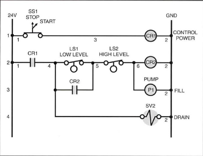
Relay Based On Off Controller Level Control from levelprocesscontrolsystem2.weebly.com It does this turning on and off a water pump depending on the status of sensors. Technical explanation for level controllers. This video is about fully automatic water level controller pcb kit with all awesome features like dry run sensor, source tank. The ends of probes are connected to corresponding points in the circuit as shown in circuit diagram. Using this water level indicator device, you can easily measure the different levels of water in the water tank so that you can turn the motor off and on accordingly. A simple but very reliable and effective water level controller circuit diagram is shown here. The circuit of water level controller id designed and the successful working verified. Automatic water level controller circuit is a simple engineering electronic.
The trigger pin of the ultrasonic sensor is connected with pin number 7 of the arduino.
Certain provisions are provided in the tank, so that we can automatically control the water level. Using simple transistors and led's to determine the level of water level indicator & controller: You are able to utilize this motor. Automatic water level controller circuit is a simple engineering electronic. The circuit uses 6 transistors, 1 ne555 timer ic, a relay and few passive components. Automatic water tank level controller with dry pump run protection using arduino + ultrasonic sensor. Pc is connected to the rest of the system via the. The automatic pump controller minimizes the need for any manual switching of water pumps installed for the functionality of pumping water from a reservoir to an overhead tank. The probes are arranged in such a way that they sense ¼th, 1/2, ¾th and even full levels as they are placed with equal spacing one. Parts list the small circuit built around ic1 draws no current and therefore no voltage drop is generated across r5. The page coolly points out a surprisingly water level controller circuit using ic 555 which could be build by just about any new hobbyist for own operation. Water level indicator circuit diagram with alarm electronic design or schematic. The trigger pin of the ultrasonic sensor is connected with pin number 7 of the arduino.