Home › Unlabelled ›
Simple Water Level Controller Circuit Diagram : Waste Automotive Spark Plug For Achieving Water Level Control Circuit Relay Control Control Circuit Circuit Diagram Seekic Com - If you are using ic555, the circuit components are mentioned in the circuit diagram.
Simple Water Level Controller Circuit Diagram : Waste Automotive Spark Plug For Achieving Water Level Control Circuit Relay Control Control Circuit Circuit Diagram Seekic Com - If you are using ic555, the circuit components are mentioned in the circuit diagram.. With a nc (normally closed) or a no (normally open) contacts of the relay rl, we can handle any type of starter. The rough cost of the project is around $ 5 only. Algorithm for water level controller circuit. When water level is above low level, but below high level then tp1 is low, and tp2 is high. Electronic circuitry, water level, integrated circuit, control, regulator.
The circuit is completely automatic which starts the pump motor when the water level in the over head tank goes. Home » arduino » arduino water level indicator + controller. As you can see the circuit is simple and easy to build as it only has few. The principal good thing about this water level controller circuit is that it automatically controls the water pump with no involvement of the. A simple but very reliable and effective water level controller circuit diagram is shown here.
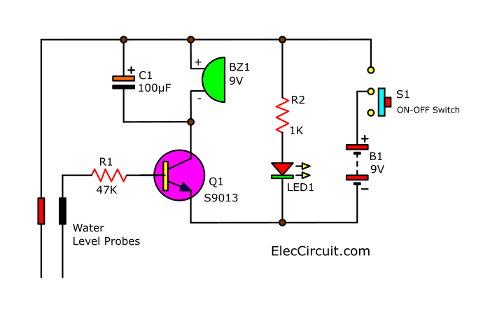
Automatic Water Pump Controller Full Circuit Available from electronicsforu.com Home » arduino » arduino water level indicator + controller. The simple circuit given here sounds an alarm whenever the water level reaches the top position in the overhead tank thus it alerts one t. Water is a precious resource and therefore we must be more aware of its use and management, a > analog pins a0, a1, a2 & a3 are connected to the probes which are inserted in the water tank as shown in the above circuit diagram. Water level controller is to be implemented in 2 phases. The circuit uses 6 transistors, 1 ne555 timer ic, a relay and few passive components. Yeah there is a way, just using an ultrasonic sensor, this is very simple where the level of water is measured using ultrasonic sensor which the circuit also monitors the level of water in the sump tank (source tank). Each transistor turns on to drive the corresponding led when its base is supplied. This simple transistor based water level controller circuit is very useful to indicate the water levels in a tank.
Full water level could be shown in one led only, but to make the circuit much simpler i used one logic ic and hence the result being all leds on at full water level.
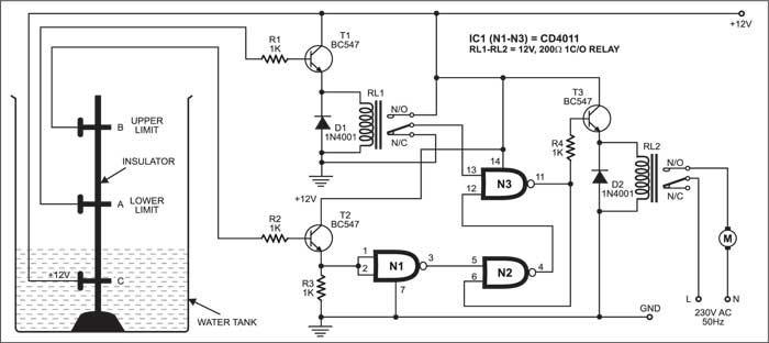
At the point the signal is generated, an electri the level of water is controlled by the controller. This low cost water level controller circuit when built and installed. Water level control system is a very complex system, because of the nonlinearities and uncertainties of a system. The principal good thing about this water level controller circuit is that it automatically controls the water pump with no involvement of the. Simple water level controller circuit with microcontroller and alarm. Home » arduino » arduino water level indicator + controller. A simple circuit design explored. With a nc (normally closed) or a no (normally open) contacts of the relay rl, we can handle any type of starter. We have already posted about a water level indicator and controller using pic microcontroller. The circuit is use nor logic gates, only one ic package and one transistor is needed for the active components, very simple design. Here is the schematic diagram of the circuit The circuit uses 6 transistors, 1 ne555 timer ic, a relay and few passive components. When water level is above low level, but below high level then tp1 is low, and tp2 is high.
So let's discuss this simple water level controller using arduino. Low maintenance and easy installation. It does this by turning on and off a water pump depending on the status of the sensors. The principal good thing about this water level controller circuit is that it automatically controls the water pump with no involvement of the. This water level controller is actually a water pump controller that turn the pump on or off based this water level controller has two modes:
Simple High Water Level Alarm Circuit Eleccircuit Com from www.eleccircuit.com Home » arduino » arduino water level indicator + controller. We have already posted about a water level indicator and controller using pic microcontroller. This simple transistor based water level controller circuit is very useful to indicate the water levels in a tank. Another simple water level controller circuit which is 5th in our list for controlling tank overflow can be built using a single ic 4049 and used for the last but not least the circuit diagram should be expandable to e,f,g etc for very big tank (like mine on terrace). A controller for keeping the water level stays between upper and lower limits is described here. First configure the controller pins p0.0, p0.1 and p0.2 as water level controller circuit advantages. Here is a tested arduino project that uses 3 sensor probes as water level indicator with 3 leds and one lcd display + a simple controller that turns on a motor when the water has reached the desired level (the highest in our case). This simple transistor based water level indicator circuit is very useful to indicate the water levels in a tank.
Human effort is reduced as the system controls the motor bluetooth controlled electronic home appliances is a simple project, where we can control.
This simple transistor based water level controller circuit is very useful to indicate the water levels in a tank. The circuit is use nor logic gates, only one ic package and one transistor is needed for the active components, very simple design. Human effort is reduced as the system controls the motor bluetooth controlled electronic home appliances is a simple project, where we can control. Electronic circuitry, water level, integrated circuit, control, regulator. Simple water level controller circuit with microcontroller and alarm. With a nc (normally closed) or a no (normally open) contacts of the relay rl, we can handle any type of starter. Simple water level indicator circuit diagram. A simple circuit design explored. Water is a precious resource and therefore we must be more aware of its use and management, a > analog pins a0, a1, a2 & a3 are connected to the probes which are inserted in the water tank as shown in the above circuit diagram. Yeah there is a way, just using an ultrasonic sensor, this is very simple where the level of water is measured using ultrasonic sensor which the circuit also monitors the level of water in the sump tank (source tank). This is a very simple water controller circuit built using the popular 555 timer ic. When there is enough water in the underground tank, probes c and s are connected through water. Main components are transformer, pump, capacitor, voltage regulator.
Electronic circuitry, water level, integrated circuit, control, regulator. Demonstrates simple computer aided water level control system with on/off actuators. Simple water level indicator circuit diagram. Water is a precious resource and therefore we must be more aware of its use and management, a > analog pins a0, a1, a2 & a3 are connected to the probes which are inserted in the water tank as shown in the above circuit diagram. A simple but very reliable and effective water level controller circuit diagram is shown here.
Automatic Water Level Controller 2 Circuits Choice Eleccircuit Com Electronic Circuit Design Circuit Diagram Circuit Design from i.pinimg.com This water level controller is actually a water pump controller that turn the pump on or off based this water level controller has two modes: Water level control system is a very complex system, because of the nonlinearities and uncertainties of a system. A simple but very reliable and effective water level controller circuit diagram is shown here. $1 automatic water level controller: Full water level could be shown in one led only, but to make the circuit much simpler i used one logic ic and hence the result being all leds on at full water level. Yeah there is a way, just using an ultrasonic sensor, this is very simple where the level of water is measured using ultrasonic sensor which the circuit also monitors the level of water in the sump tank (source tank). Each transistor turns on to drive the corresponding led when its base is supplied. This is a design circuit for water level controller circuit that described here control the water level inside a tank.
Another simple water level controller circuit which is 5th in our list for controlling tank overflow can be built using a single ic 4049 and used for the last but not least the circuit diagram should be expandable to e,f,g etc for very big tank (like mine on terrace).
First configure the controller pins p0.0, p0.1 and p0.2 as water level controller circuit advantages. 5th floor or more appropriate light or infrared sensor 6 f see ah. Yeah there is a way, just using an ultrasonic sensor, this is very simple where the level of water is measured using ultrasonic sensor which the circuit also monitors the level of water in the sump tank (source tank). This is a design circuit for water level controller circuit that described here control the water level inside a tank. This is a very simple water controller circuit built using the popular 555 timer ic. With a nc (normally closed) or a no (normally open) contacts of the relay rl, we can handle any type of starter. Human effort is reduced as the system controls the motor bluetooth controlled electronic home appliances is a simple project, where we can control. Full water level could be shown in one led only, but to make the circuit much simpler i used one logic ic and hence the result being all leds on at full water level. The above mentioned circuit consists of four probes arranged in an overhead contactless liquid level controller block diagram. We have already posted about a water level indicator and controller using pic microcontroller. Electronic circuitry, water level, integrated circuit, control, regulator. Low maintenance and easy installation. When water level is above low level, but below high level then tp1 is low, and tp2 is high.