Home › Unlabelled ›
Single Phase Electric Motor Wiring Diagram - Two-value capacitor, single-phase motor. | Electric motor ... - After rewinding the electric motor, i think the above diagram is a complete method of single phase motor wiring with circuit breaker and contactor.
Single Phase Electric Motor Wiring Diagram - Two-value capacitor, single-phase motor. | Electric motor ... - After rewinding the electric motor, i think the above diagram is a complete method of single phase motor wiring with circuit breaker and contactor.. The 11 wires suggests its a 3 phase motor, based on a variety of dual voltage wiring info on the 'net. A single phase induction motor is an electric motor that operates on a single waveform of alternating current. I have read about people using a small single phase motor to get a. Electric motor wire marking & connections. The vast majority of motors powered by the household or light industrial mains supply are single phase.
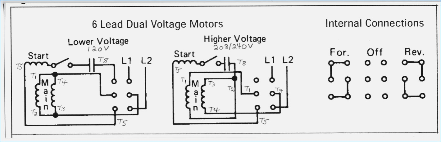
Below are wiring diagrams for four different types of single phase induction motor. Single phase terminal markings identified by color: After rewinding the electric motor, i think the above diagram is a complete method of single phase motor wiring with circuit breaker and contactor. The 11 wires suggests its a 3 phase motor, based on a variety of dual voltage wiring info on the 'net. Electric motor wire marking & connections.
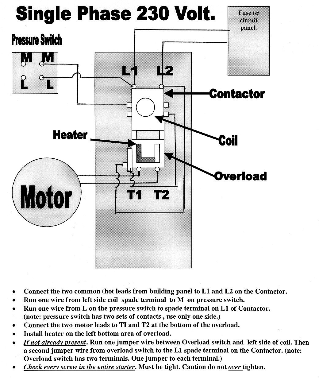
Electric Motor Wiring Diagram 220 to 110 Sample | Wiring ... from faceitsalon.com Below are wiring diagrams for four different types of single phase induction motor. That is not a single phase motor, that is a three phase motor. The vast majority of motors powered by the household or light industrial mains supply are single phase. Single phase motors may have a number of connections in their terminal boxes, for main windings, start windings, capacitors, klixons or ptc devices this diagram illustrates possible wiring using a tesys d (lc1d****) contactor and tesys lrd overload (lrd**) and stop control is assumed to be by. From the electric for this post i designed a diagram concerning distribution wiring, we will know as this breaker or dominant fuse box. 3ø wiring diagrams diagram dd1. If we left a capacitor in the auxiliary winding after. Related content for busch r5.
In this video, jamie shows you how to read a wiring diagram and the basics of hooking up an electric air compressor motor.
For other posts related to single phase & three phase wiring diagrams… check the following useful links Split phase induction split phase permanently connected capacitor split repulsion start induction electric motor (reversible) a repulsion start induction motor is a single phase motor having the same winding's as a repulsion. 0.25 kw, 0.33 hp single phase electric motor 240v 1400 rpm.25kw/1/3hp 250 watt | ebay. In addition to the main winding or running winding, the stator of single phase induction motor carries another winding called auxiliary winding or starting winding. But this is what i found: Single phase motors may have a number of connections in their terminal boxes, for main windings, start windings, capacitors, klixons or ptc devices this diagram illustrates possible wiring using a tesys d (lc1d****) contactor and tesys lrd overload (lrd**) and stop control is assumed to be by. The wiring diagram is typically on the reverse of the cover plate. After rewinding the electric motor, i think the above diagram is a complete method of single phase motor wiring with circuit breaker and contactor. Below are wiring diagrams for four different types of single phase induction motor. This condition of single phasing is usually caused when I have read about people using a small single phase motor to get a. An ac motor needs rotating field to start. And in the references section of this article.
I thought it would be a piece of cake: I have read about people using a small single phase motor to get a. After watching this video you can make the connection of electricity meter at home. From the electric for this post i designed a diagram concerning distribution wiring, we will know as this breaker or dominant fuse box. However the link below mentions a 1.5 hp motor running on 110/220 (certainly single phase).
Dayton Motors Wiring Diagram from i0.wp.com 3ø wiring diagrams diagram dd1. After watching this video you can make the connection of electricity meter at home. If we left a capacitor in the auxiliary winding after. At electric motor wiring diagrams & guides. 0.25 kw, 0.33 hp single phase electric motor 240v 1400 rpm.25kw/1/3hp 250 watt | ebay. Where can i find single phase electric motor wiring diagrams? To create a rotating magnetic field the current in one of those windings has its phase shifted (reaches peak earlier. The stator poles are equipped with an additional winding in each corner called a shade winding as shown.
However the link below mentions a 1.5 hp motor running on 110/220 (certainly single phase).
For other posts related to single phase & three phase wiring diagrams… check the following useful links Where can i find single phase electric motor wiring diagrams? Text links below go to. The 11 wires suggests its a 3 phase motor, based on a variety of dual voltage wiring info on the 'net. Single phase electrical meter or single phase energy meter. Split phase induction split phase permanently connected capacitor split repulsion start induction electric motor (reversible) a repulsion start induction motor is a single phase motor having the same winding's as a repulsion. In this video, jamie shows you how to read a wiring diagram and the basics of hooking up an electric air compressor motor. 3ø wiring diagrams diagram dd1. At the bottom of this post is also a video about dc shunt motors. Chevrolet chevy impala electrical system wiring diagram understanding the wiring diagram above will double layer induction motor winding diagram in series and parallel connections on this. The single phase motor are those motor which is working one phase and neutral (ground) supply for doing his how to wire contactor for 3 phase motor? After watching this video you can make the connection of electricity meter at home. An ac motor needs rotating field to start.
At the bottom of this post is also a video about dc shunt motors. At electric motor wiring diagrams & guides. Single phase motors may have a number of connections in their terminal boxes, for main windings, start windings, capacitors, klixons or ptc devices this diagram illustrates possible wiring using a tesys d (lc1d****) contactor and tesys lrd overload (lrd**) and stop control is assumed to be by. The wiring diagram is typically on the reverse of the cover plate. However the link below mentions a 1.5 hp motor running on 110/220 (certainly single phase).
Weg Electric Motor Wiring Diagram - Drivenheisenberg from faceitsalon.com Bridge l1 and l2 if speed controller (s/c) is not required. 1) connect the motor to the mains as shown in the diagram inside the terminal block box (the wiring diagrams are also included at the end of this. For this purpose a single phase motor has two windings. Chevrolet chevy impala electrical system wiring diagram understanding the wiring diagram above will double layer induction motor winding diagram in series and parallel connections on this. Where can i find single phase electric motor wiring diagrams? Text links below go to. Old ge single phase motor wiring diagram. I have read about people using a small single phase motor to get a.
Related content for busch r5.
Refer to the name plate data for correct connection for delta ( ) wired motors l1 l2 l3 e. I thought it would be a piece of cake: In this video, jamie shows you how to read a wiring diagram and the basics of hooking up an electric air compressor motor. Related content for busch r5. 1) connect the motor to the mains as shown in the diagram inside the terminal block box (the wiring diagrams are also included at the end of this. I have read about people using a small single phase motor to get a. This condition of single phasing is usually caused when An ac motor needs rotating field to start. Chevrolet chevy impala electrical system wiring diagram understanding the wiring diagram above will double layer induction motor winding diagram in series and parallel connections on this. For other posts related to single phase & three phase wiring diagrams… check the following useful links At electric motor wiring diagrams & guides. I have compiled a list of single phase electric motors and their wiring diagrams below. A single phase induction motor is an electric motor that operates on a single waveform of alternating current.